BB Function Description
Data extracted from DepatisNet Dokument WO001988008564A1
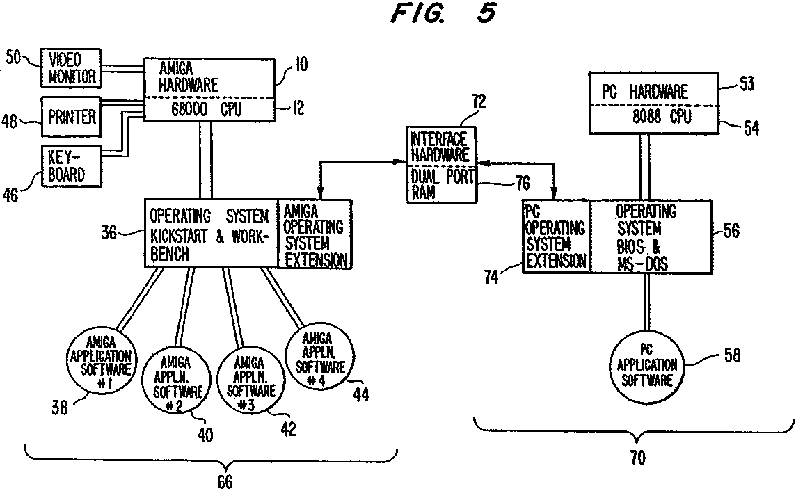
Co-processor computer system 70 in Fig. 5 includes hardware and software necessary to create a PC environment and also includes PC application software to run in that environment.
Specifically, co-processor computer system 70 is a PC-type interrupt driven computer system with an 8088 CPU 54, RAM ROM, and support chips less peripherals and includes a PC operating system
extension 74 discussed below. (Monochrome and color graphics adapters are also included in the co-processor computer system. The remainder of the co-processor system is emulated on the host system side of the interface hardware.
Specifically, to run a PC application program, the Amiga system re-configures the data being generated by input on keyboard 46 to appear as PC keyboard data for use by the PC system. The Amiga system also emulates a PC printer port on its own parallel port so that the PC system can use printer 48, and displays the PC video output in both monochrome and color on video monitor 50.
To facilitate PC application software compatibility in host computer system 66, interface hardware 72 is used between the host computer system and the co-processor computer system. The operating system extensions 68 and 74 manage and use
interface hardware 72 to allow rapid interprocesor communication between CPU 12 of the host computer system 66 and CPU-54 of co-processor computer system 70. The main component of interface hardware 72 is a dual port random access memory 76
(DPRAM) connected to the data and address buses of the two CPUs 12, 54. This memory is shared by both CPUs to accomplish communication between the CPUs.
Other memories. of course,could be used as long as access can be made from more than one port. Such a memory, for the purposes of this disclosure, is called a dual port memory. With the two operating system extensions 68, 74, interface hardware 72 is controlled to make the hardware appear transparent to the user of host computer system 66 and also transparent from the co-processor computer system side of the interface hardware.
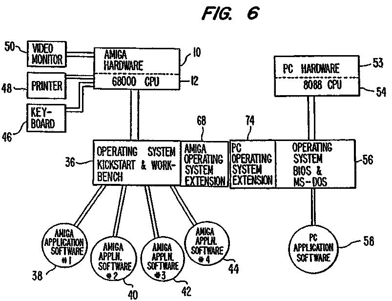
In operation, the entire system appears from the two CPUs as a single co-processing system illustrated in Fig. 6 In-this system, a task requested in either of the computer systems 66, 70 can, of course, communicate directly with its
respective operating systems 36, 56.
Additionally, however, any task requested in one operating system can communicate to the operating-system.of the other computer system and request that the processing system perform the requested task.
For example, if a specific task is requested in the host computer's operating system 36 requesting that PC operating system 56 execute a specific function, the operating system can communicate with interface hardware 72 via operating system extension 68
and set up parameter data in a specified are of the DPRAM of the interface hardware to perform.the requested function.
Operating system 36 causes an interrupt to be transmitted to co-processor system 70 which interrupt indicates to the co-processor system the type of function requested.
The interrupt-driven co-processor computer system accepts the function request and performs the necessary program based on the interrupt received to execute the function, including accessing the parameter data in the DPRAM which is included in-the interface
hardware 72. Upon the completion of the execution, co-processor computer system 70 returns an acknowledgment through its operating system extension 74 and interface hardware 72 to provide an interrupt to operating system 36.
This.acknowledgement notifies operating system.36 that the requested function has been completed. Similarly, from the co-processor computer system side, a PC application program can run, for example, output data to be displayed on a video monitor.
As discussed later, that data is then placed into the appropriate DPRAM location, particularly into the video RAM portion to the DPRAM. That action of the co-processor system causes an interrupt to issue to the host computer system 66 which recognizes
it as a video memory interrupt.
In accordance with the issued interrupt the host system then accesses the appropriate location in DPRAM 76 and processes the video memory into the host computer system's video monitor 50.
The interface between host computer system 66 and co-processor computer system 70 provided by interface hardware 72 is interrupt driven. All functions in the computer systems are requested by interrupts. Hardware in interface hardware 72
automatically issues hardware interrupts to host CPU 12 or co-processor computer system 70 or host computer system 66, respectively. Furthermore, software applications can define new classes of events which allow either of the computer systems to
use the facilities of the other, thereby creating an extended multiprocessor environment.
When data is to be exchanged between the two computer systems, it is transmitted via DPRAM 76. By using interrupts and a "lock byte" system discussed below to manage communications, both computer systems can operate completely independent
of each other without degradation of performance.
In the preferred embodiment, predefined events occurring in co-processor computer system 70 which generate hardware interrupts to be acted upon by the host computer system can include requests by the co-processor computer system to access
the color video memory of DPRAM 76, access the mono-chrome video portion of the DPRAM, access the mono CRT register, accessor the color CRT register, access the line printer register, access the serial data register, and read the keyboard
register. Predefined events from the host computer system which force interrupts on the co-processor computer system, in the preferred embodiment, can include accessing the keyboard register, accessing the serial data register, and accessing the
line printer register.
Concerning custom software defined interrupt events, they can be added to allow the programs on both sides of interface hardware 72 to communicate in any way desired. This could include, for example, code execution by one of the CPU‘s,
including full access to all system functions of each Operating system. The CPU of the co-processor computer system could, for example, create a task in the host computer system's multi-tasking environment and then instruct the task to execute host
computer system library calls. The host computer system, in turn, can request software interrupts on the co-processor computer system.
If the reason for an interrupt is not one of the predefined events discussed above, the computer system which is being called on to take action by the other computer system must be informed with information on the appropriate function to undertake.
These non-predefined events or logical events require the use of parameter blocks as discussed below
It should be noted that in the above described operations, all function interrupts come in pairs, that is an initial interrupt when a function is requested by one of the CPUs and an acknowledgment interrupt from the other when the request has been satisfied.
Thus, each CPU can issue a function request and then continue with other processing until the requested function is acknowledged. This allows completely asynchronous operation of both systems.
Interprocessor communication between CPU 12 of host computer system 66 and CPU 54 of co-processor computer system 70 is facilitated by the DPRAM connected to the CPU buses of the CPUs in both the host and the co-processor computer systems.
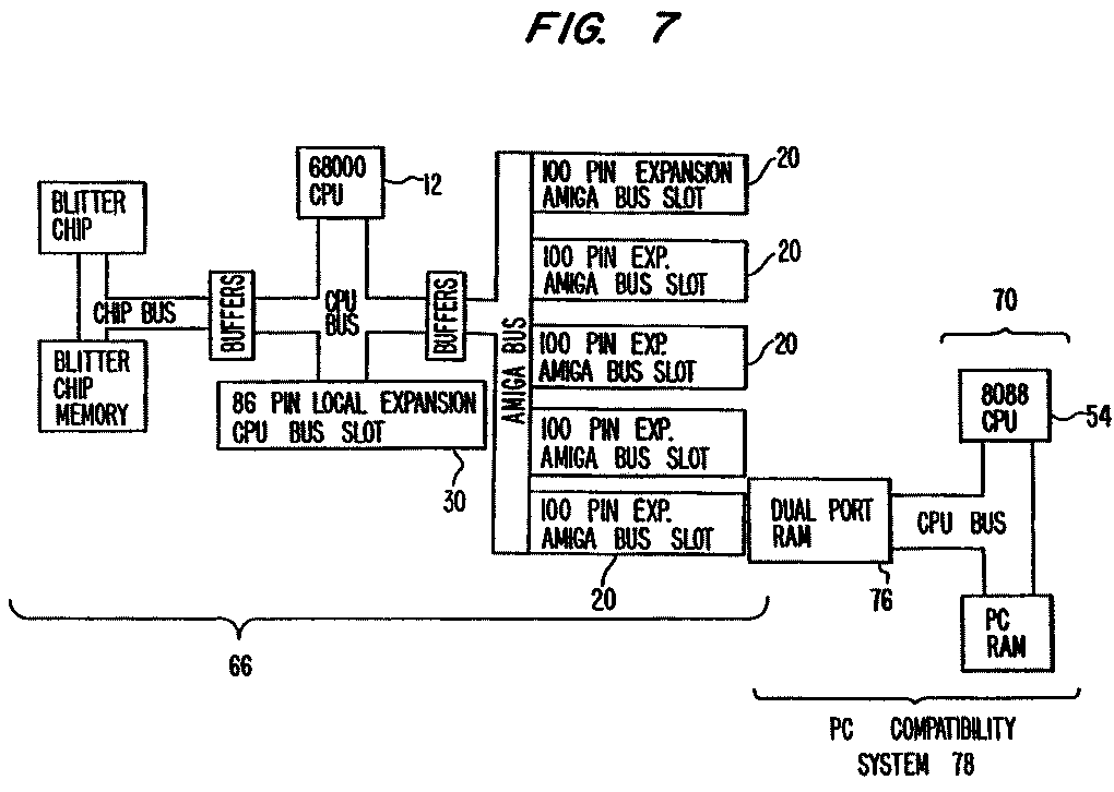
The positioning of the DPRAM with respect to the host computer system and the co-processor system is shown in Fig. 7. Specifically, DPRAM 76 is connected to both the Amiga bus and the CPU bus of the co-processor system.
(Not all of the hardware of co-processor system 70 is illustrated in Fig. 7.)
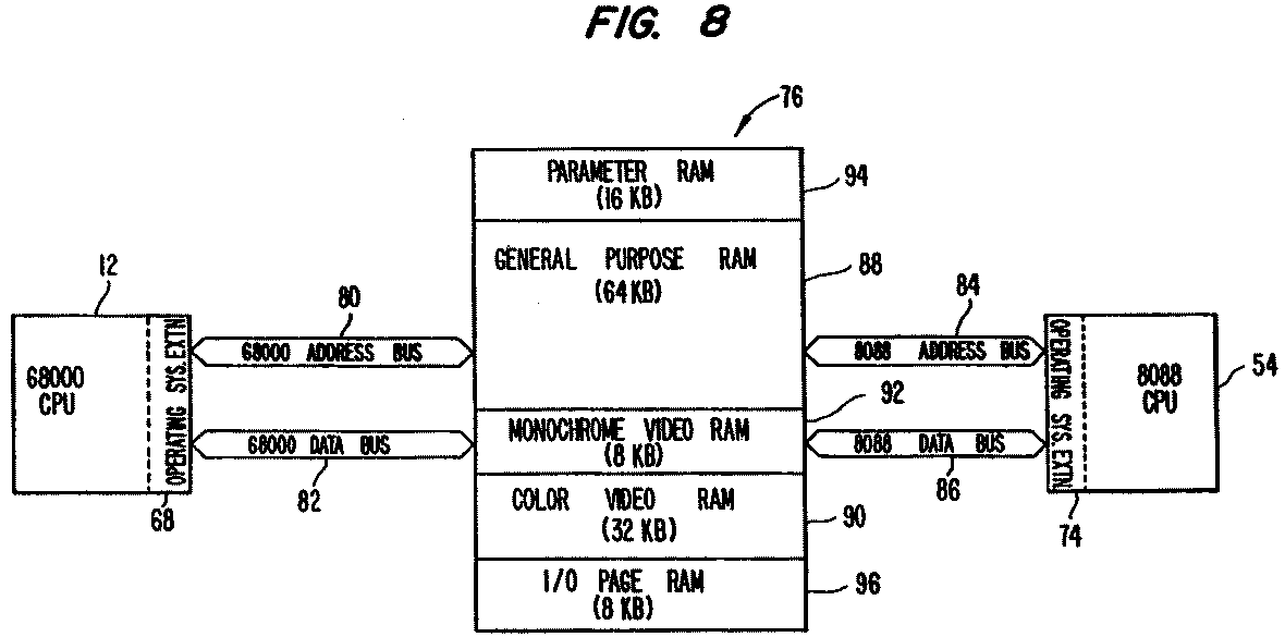
 In Fig. 8, details of DPRAM 76 are shown along with its association of the host and co-processor computer systems and their CPU buses. As shown in Fig. 8, the Amiga bus includes 68000 address bus 80 and 68000 data bus 82, and the coprocessor bus includes the 8088 address bus 84 and 8088 databus 86. DPRAM 76, in the preferred embodiment, is a 128K byte memory into which data is transferred from one of the computer systems for use by the other of the computer systems.
As also shown in Fig. 8, different portions of the DPRAM are reserved for specific uses. General purpose RAM area 88 is a 64K byte area used as a general purpose buffer; color video RAM 90 is a 32K byte area used for PC color video memory; and monochrome video RAM 92 is an 8K byte area for PC monochrome video memory.
In DPRAM 76, a 16K byte area is designated as aparameter RAM 94. Parameter RAM 94 provides two functions.
- First, both the host computer 66 and the co-processor computer 70 use one byte of parameter RAM 94 to assist the two systems in successfully sharing the DPRAM. Specifically, the byte is a "lock byte" used by either of the computer systems to signal that a new portion of general purpose RAM 88 is being allocated or freed. A check of this lock byte by one of the computer systems indicates whether the other of the computer . systems is allocating data to a portion of the memory or is freeing a portion of the memory. If that is the case, the computer attempting to allocate or free a portion of the memory will wait until the other system is completed in its allocating or freeing and has so indicated that completion by configuring the lock byte to the "unused" status.
- The second function of parameter RAM 94 is to hold blocks of parameters set by one computer which the other computer reads. For example, when host computer system 66 desires an action which is not one of the preferred events discussed above which automatically generates the appropriate hardware interrupt, for example, the transfer of a block of data to co-processor system 70, the transferring data is read into.and held by general purpose RAM as of DPRAM 76 until that data is read out of that address by co-processor system 70. Parameter RAM 94 holds information necessary to perform the transfer, for example, the length and location of the data to be transferred and the desired destination of that data in the co-processor system, which information has been set by the computer requesting the transfer, in this instance, host computer 66.
Also included in DPRAM 76 is a final 8K byte area designated the I/0 page RAM 96. It is used to perform various services such as mapping certain address ranges on the host computer system side of the interface hardware. On the co-processor system side of the hardware the I/O page RAM area contains a standard set of I/O register locations for the co-processor system that are used to control the serial and parallel ports and the PC monochrome and color CRT controller.
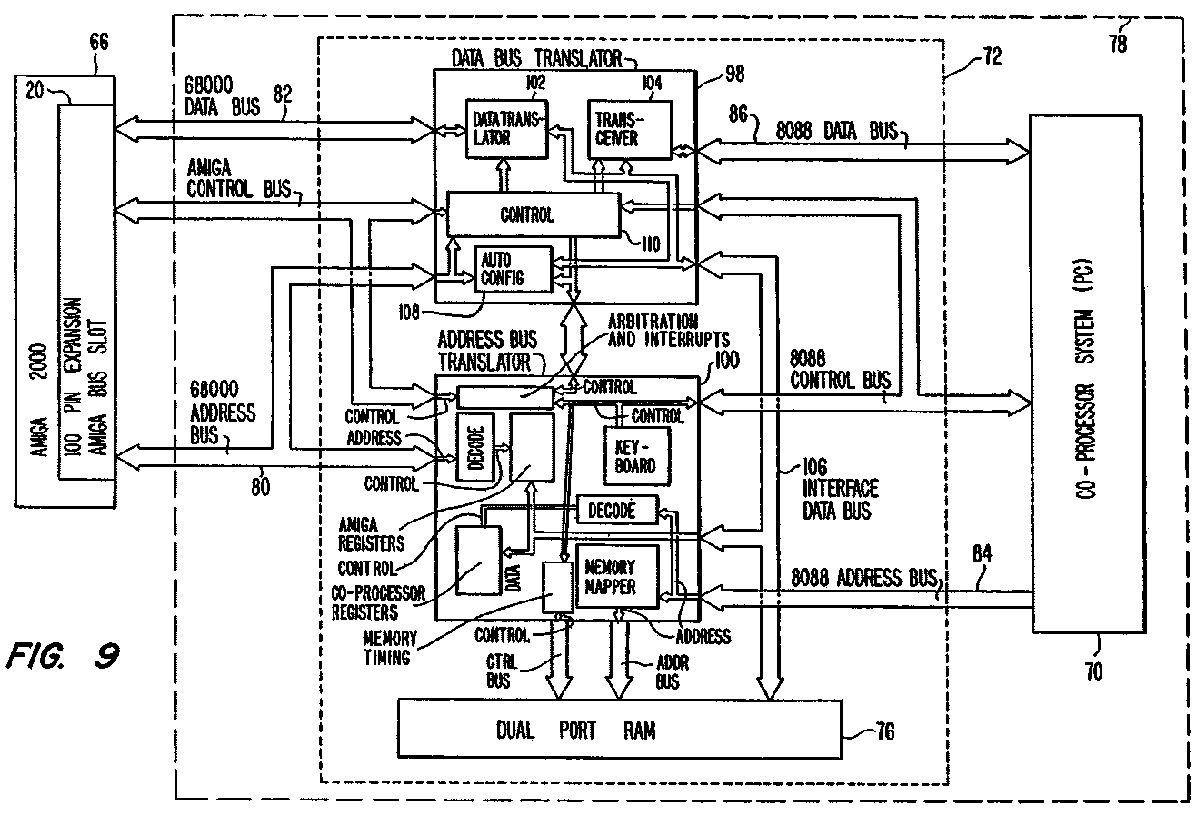
In the preferred system described herein concerning an Amiga computer system as host computer system 66 and the co-processor system 70 which creates a PC-environment for running PC application software, two support chips are provided to wassist in the interprocessor communication achieved through the sharing of DPRAM 76. The details of those chips in interface hardware 72 are shown in Fig. 9. The two chips, called data bus translator ("DBT") 98 and address bus translator ("ABT") 100, are shown in block diagrammatic form connected to the CPU buses and control buses of both host computer system 66 and PC compatible co-processor computer system 70.
DBT 98 functions as a data bus transceiver for 68000 data bus 82 and for the 8088 data bus 86 to interface those data buses with DPRAM 76.
More specifically, DBT 98 contains data translator 102 which functions to interface the 68000 CPU 12 of the host computer system to-the DPRAM. Specifically, data translator 102 provides three transfer mechanisms. First, a wordtransfer operation is provided to realign bytes in. accordance with individual processor requirements of the host and co-processor systems. Host CPU 12 stores the most significant byte at the low-order address while co-processor CPU 54 stores the most significant byte at the high-order address.
Data translator 102 provides this word transfer mechanism to make realignment automatic whenever data is written across interface hardware 72. Thus, this realignment places data in one of the computer systems into a format usable by the other system. Second, data translator 102 provides byte transfer operations which transfer data straight across the interface hardware without the byte swap which occurs in the word transfer operation described above. Third, data translator 102 also provides a graphics transfer mechanism which is used to separate PC graphics data into discrete bit planes required by the host computer system. The graphics transfer mechanism substantially reduces the amount of software overhead necessary to display PC graphics on video monitor 50.
A specific example of the graphics transfer mechanism is illustrated and discused in an article titled "The Commodore A2000" found at pages 84-98 of the March 1987 issue of BYTE magazine.
Transceiver 104 of DBT 98 functions as a high-speed data-transceiver. It is used to steer bidirectional data
transfers from the 8-bit 8088 data bus 86 to the 16-bit DPRAM interface data bus 106. Auto config 108 of DBT 98 provides an autoconfiguration protocol which is used to insure that peripheral boards are installed into the system at boot-up.
Autoconfig 108 automatically configures the co-processor system 70 into the host computer system 66 memory map during system boot. Finally, control 110 of DBT 98 functions to provide control signals for driving the various functions performed in DBT 98.
Control 110 contains the base address comparator, address decoders, and other circuits which support the interface hardware operation.
The second chip in interface hardware 72 is ABT 100. It provides PC address translation, DPRAM arbitration, interrupt control-logic, and keyboard emulation.
Concerning address translation, ABT 100 translates co-processor system memory and I/O addresses into appropriate locations in the memory map of DPRAM 76 shown in Fig. 8. Any I/0 request recognized by the ABT 100 as being I/O device emulated by the host computer system 66 triggers the translation function.
For example, if host computer system 66 on the parallel port emulation and co-processor system 70 attempts to write to the printer data port, ABT 100 will generate the address for the printer data port's location in DPRAM 76. ABT 100 also maps various co-processor system memory requests into DPRAM 76, for example, video memory
accesses to monochrome video RAM 92 or color video RAM 90 of the DPRAM show in Fig. 8 Concerning the DPRAM arbitration, ABT 100 arbitrates access requests to DPRAM 76 between host computer system 66 and
co-processor system 70. The two computer systems utilize independently generated clocks, thus requiring DPRAM requests to be synchronized to prevent conflict. Normally, the requests are serviced on a first-come, first-serve basis as discussed above.
ABT 100 also provides DPRAM timing signals and DPRAM refresh signals as necessary.
With respect to the interrupt control logical function of ABT 100, when either one of the computer systems places
information in DPRAM 76 as a predefined event, ABT 100 generates an interrupt to the other one of the computer systems as necessary. In the printer port example described above, an interrupt to host computer system 66 will occur to inform that system, by its reading ofla register in ABT 100, that the printer data has been updated so that the host computer system 66 will take appropriate action on that data.
The last function of ABT 100 concerns keyboard emulation.
Since the system described.here uses keyboard 46 of the host system for data input to the co-processor system 70,the
keyboard input from keyboard 46 must be translated into a keyboard equivalent for loading DPRAM 76 so that co-processor system 70 can utilize the information. Thus, another function of ABT 100 is to serialize the keyboard data received from host computer system 66 for use in co-processor system 70. Specifically, the.Amiga host system loads an ABT register with a byte of keyboard data from keyboard 46. Thus, the ABT encodes the data serially for use by the co-processor system.
PC compatibility system 78 has been described in association with Fig. 9 for the host computer system 34. The system is connected to the CPU bus of the host computer system and allows true PC displays to be intermixed with all the displays available on the host computer system itself. The PC video information can be displayed in standard windows of the
multi-tasking host computer system. Additionally, all PC video modes are supported, that is monochrome and color text and
color graphics, which can be displayed simultaneously in different windows on host video monitor 50.
In the system described above, the video portion of the co-processor system memory is mapped directly into monochrome video RAM 92 or color video RAM 90 of DPRAM 76. That writing is a predetermined event and is performed by the co-processor system BIOS screen I/0 routines. Thus, the co-processor system action causes the transmission of a hardware
generated interrupt signal to the host computer system which informs that computer system that there has been activity in
the video memory portion, that is portion 90 or 92 of DPRAM 76 and the host system acts accordingly on that data.
Since this mapping is transparent to co-processor system 70, the video display is-completely compatible both to applications that use the ROM BIOS in the co-processor system and to applications that word directly with the with the video memory in that system. Meanwhile, software running on the host system 66 can use the video data mapped directly into DPRAM 76 to create windows on Amiga video monitor 50 that emulate faithfully video generated in co-processor system 70. By using two different portions of the DPRAM for video memory, that is monochrome
video RAM 92 and color video RAM 90, both monochrome and color graphics can be emulated at the same time and shown on the video monitor.
In addition to the video display enhancement provided by the system, due to the interface hardware and supporting
software, the host system's keyboard 46 and serial and parallel ports 24; 26 can be used by the PC co-processor system as discussed above.
To further assist in explaining the method of the present invention, two specific examples of typical communications between the CPUs of the host and co-processor systems are provided. They are given only for exposition and are not to be taken as limiting the claimed invention.
- In a first example, the method of communicating a monochrome or color video display from co-processor system 70
to video monitor 50 on the Amiga host system 66 is discussed.
In this example, a PC "Flight Simulator" program is running on the co-processor system which is to be displayed in the video
monitor on the host system. When the "Flight Simulator" program outputs data to be read on a video monitor, the co-processor system using its BIOS screen I/O routines as discussed above writes the information into the monochrome video
memory 92 or into color video memory 90 of DPRAM 76 as determined by the specific output data.
The computer system requesting the operation, that is co-processor system 70, has therefore requested a function to
be performed and has transferred the data to the DPRAM. Since the function desired by the requesting computer is one of the
predefined events a hardware interrupt issues to the other one of the two computer systems, that is, host computer system 66 in this example. ‘The interrupt indicates to the host computer system the type of function requested, that is, a video memory request. At that time the host computer system acting on the informative interrupt accesses the data in the appropriate video RAM portion of DPRAM 76 and acts on the data contained therein. For example, the host system updates the PC video display shown on host computer system video monitor 50.
The host system, upon.completion of the requested function, informs the requesting computer system (in this instance, co-processor system 70) by way of acknowledgment that the requested function has been completed. That acknowledgment initates the erasing of the data temporarily stored on the DPRAM.
An example of the interprocessor communication using parameter RAM 94 of DPRAM 76 is as follows. In this example, the requesting computer system is the host computer system which wishes to write a block of data into the specific portion of the memory in cosprocessor system 70. Also in this instance, the s ecific function is a "peek poke" memory function.
When the peek/poke function is requested in host computer system 66, the host computer system generates data representing the requested function and, in this instance would request allocation of memory in parameter RAM 94 and in general purpose RAM 88 of DPRAM 76. Then, the host system provides the data on how the function is to be performed to DPRAM 76.
Specifically, the data would include the address in the co-processor system to be written, how many bytes of data are to be transferred, and where in the general purpose RAM the actual data is stored.
The actual data is then transferred from the host system into the designated portion of general purpose RAM 88. That data is temporarily stored in the DPRAM.
At this time, the host system calls the peek/poke memory function and issues an interrupt to the interrupt driven co-processor system 70; When the interrupt is received by the co-processor system, that system will be informed that the host
system desires the transfer of data-to the co-processor system and, therefore, the co-processor system takes action to examine parameter RAM 94 for data on the specific function requested.
Using that data, the co-processor system locates in and transfers the data from general purpose RAM 88 to the designated final location within the co-processor system. After that data has been transferred, the co-processor generates and transfers an acknowledgment of completion to the host system. At that time, the memory in DPRAM 76 allocated for the specific function is cleared so that the memory will be available for other tasks.
In the above described system, a method is provided to allow the high performance host computer system to utilize
PC application software as desired. Thus, the user of the host system can enjoy the available library of PC application programs which otherwise would be unavailable. Furthermore, the user can process the PC programs in a multi-tasking environment using enhanced graphics made capable by the host system.
It will become apparent to those skilled in the art that various modifications and variations can be made in the
method of communicating data between the CPU of the host computer system and the CPU of a co-processor computer system of the present invention without departing from the scope or spirit of the invention. Thus, it is intended that the present
invention covers the modifications and variations of this invention provided they come within the scope of the intended
claims and their equivalence.
Last Change: 23.06.2023
